Multiphysics Displayed in Origin 7.5:
Laser Synthesis of Nanoparticles
Dr. James Gardner
Environmental Instruments, Corp.
Summary
Dr. James Gardner, a consultant in nanotechnology and multiphysics
engineering, has designed a nozzle to be used in the fabrication
of integrated optics on ø100mm silicon wafers.
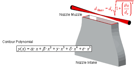
 Illustration
of the nozzle/laser setup
 A designed laminar flow nozzle issues reactants into
a focused laser beam. The fluid and laser interpenetrate orthogonally.
Critical nozzle geometry was derived using Computational Fluid Dynamics
(CFD) code. To verify the computational model, Hot Wire Anemometry
(HWA) was used to measure the fluid velocity profile. The goal was
to design a nozzle that had a top-hat velocity profile (not the
standard laminar parabolic) relative to the focused laser beam thickness.

|
Making Presentation Quality Graphs
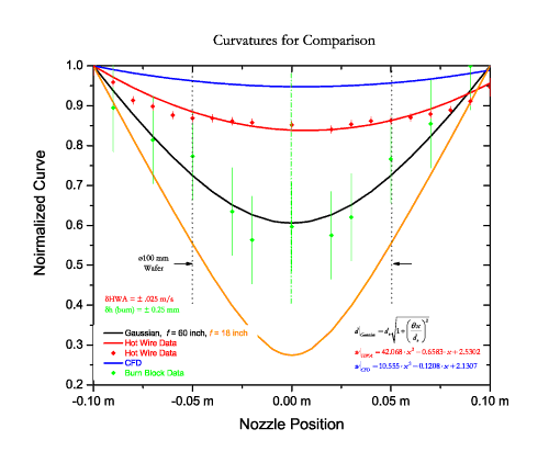
Computational model, theory and experiment are shown in a
single Origin scatter plot. The graph shows nozzle muzzle
position versus normalized ordinate data. As the physical
units of the ordinates are dissimilar, their values were divided
by their respective maximum value to show the relative variance
across the nozzle. The graph includes the following plots:
Theoretical:
- The BLACK line is the Gaussian beam waist through
a 60 inch focal length refractive optic. The equation noted
in black in the bottom right corner of the graph is the
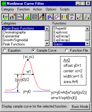
result. The Origin nonlinear curve fitter was used to generate
this curve.
- The ORANGE line is the Gaussian beam waist through
an 18 inch focal length refractive optic. This was used
as a comparison of off-the-shelf optics. Note the shorter
focal length yields a shorter 'collimated' length (Rayleigh
range).
|
|
 |
Computation:
- The BLUE line is the Origin second-order polynomial curve
fit to the locus of computational model prediction of velocity
profile. The model generates a velocity vector every two millimeters.
The vector magnitudes are then fit to the second-order polynomial.
The equation that describes the blue curve fit line is also in
blue labeled wCFD.
Experimental:
- The RED Scatter plot is the actual HWA data of the muzzle
velocity profile. HWA is a technique that immerses a thin wire
in a flow stream. A current is applied to the wire thereby heating
the wire. The current required to maintain the wire temperature
is proportional to the convective cooling of the wire by the flow
stream. This convective heat loss is directly proportional to
the flow stream velocity. Each data point is the average value
of 1,024 measurement (1Kbyte) taken at a 1KHz frequency. The error
bars are the standard deviation of those 1,024 points. The legend
shows this as the red diamonds labeled Hot Wire Data.
Again, Origin's polynomial curve fitting was used to generate
the curve fit of the red data scatter plot shown as the RED line.
If the model and experiment were in perfect agreement, the blue
and red line would be coincident. In this case, model and experiment
have a maximum deviation of approximately ten percent. The legend
shows the curve fit as Hot Wire Data. The equation is shown as
wHWA.
- The GREEN Scatter Plot with error bars is a sanity check.
A simple test was performed to check the Gaussian beam waist calculation.
Polycarbonate blocks were placed on the nozzle muzzle at varying
positions. The laser is then shuttered rapidly to create burned
holes in the polycarbonate blocks. This procedure was performed
eleven separate times at the plotted eleven positions. The errors
bars are large due to the fact that the shutter was operated manually
and the beam exposure time varied accordingly. This varying exposure
time yielded inconsistent polycarbonate melting. After each experiment,
the melted hole was measured with vernier calipers. We can see
for the purposes of a sanity check the green data agrees with
the black calculated curve.
- Last, the diameter of a 100 mm silicon wafer is shown centered
over the nozzle center. This shows the most uniform portions of
the laser beam and reactant fluid are used for producing the most
uniform nanoparticle coating.
Other Notes:
Much use was made of Origin's extensive formatting utilities. Specifically,
utilities for drawing lines, centerlines, dashed lines and Legend
formatting was employed. The lines were created using the Line tool,
activated by clicking the Line button on the Tools toolbar (2nd
from the bottom left corner in the image seen here).
A vertical dashed/dotted green line was added to illustrate the
axis symmetry. In an ideal situation, the left and right side of
each data plot should be a mirror image. From inspection of the
plot, the data are very close mirror images about the nozzle centerline.
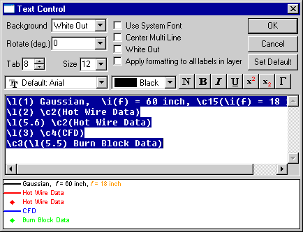
 Origin's In-place
text editing and Text Control dialog were used to customize the
Legend.
 MathType™ was used to display the equations.
Biography
Dr. James Gardner
is a nanotechnology consultant. His work crosses into many areas
including fluid mechanics, heat transference, chemical engineering,
optical engineering, and mechanical design.
MathType™ is a trademark of Design Science