|
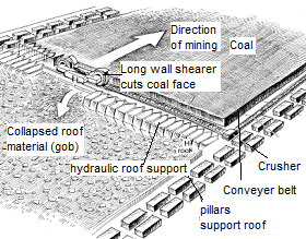
Dr. Mark K. Larson, a mining engineer at the National Institute for Occupational Safety and Health (NIOSH), uses Origin in his work as Principal Investigator for a research project on longwall mining. The project involves calibration of numerical tools that output stresses and displacements that result from mining. Longwall mining is a form of underground mining during which coal panels are mined by cutting or shearing the coal along the panel face (see figure 1). As more coal is removed, the roof of the newly excavated mine loses support and collapses. Collapse of the roof behind hydraulic roof supports at the coal face is desired to relieve stress on the coal that has not been mined yet. The numerical tools used by Dr. Larson focus on the transfer and distribution of stress between the gob (the material that collapses in the areas where the coal has already been extracted), the gate road pillars along and adjacent to the panel, and the abutments (the large blocks of un-mined coal found on the opposite side of the pillars of the panel being mined – not shown in the figure).

Figure 1. An overview of the longwall mining process
The numerical modeling tools calculate stress profiles. However, depending on the assumptions made, the results may differ from real life situations. Dr. Larson and his team compare calculated results to measured results in order to gauge the accuracy of each modeling tool and constitutive laws used. While boundary element tools such as LaModel are efficient, the number of assumptions leads to less accuracy. Volume element tools are more accurate, but this comes at a high computational cost. To handle the vast amounts of data output from the computations, Dr. Larson uses LabTalk scripts in Origin for automation of import and data manipulation. He then creates graphs in Origin to compare the measured values against the calculated values for each model.

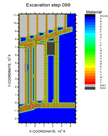
Figure 3. Contour plot of material properties indexed with character labels.
Figure 3 shows an Origin contour plot of material properties, indexed with character labels. Such graphs were created for two numerical models: MULSIM and La Model. Dr. Larson used the Set as Categorical feature to set alphabetical labels corresponding to evenly-spaced numbers as shown in the legend.
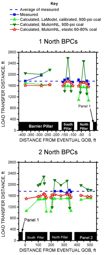
For a comparison of the measured and calculated load transfer distance, Dr. Larson and his team used Borehole Pressure Cell (BPC) measurements, and plotted the results in line and symbol graphs against the numerical models as shown in Figure 4. The similarity between the Measured curve and the Calculated, MulsimNL, elastic curve indicates that this particular model is more accurate than the other two.
In the future, Dr. Larson hopes to use Origin in another project on the calibration of numerical models for microseismic data. The calculated values will be compared to a time history of the longwall roof caving process created using measured microseismic data. Dr. Larson plans to create publication-quality graphs for journal submissions using Origin. He also hopes to explore the recently added rotation feature in Origin’s OpenGL 3D graphs as he believes this will be useful for depicting results of complicated three-dimensional models.
Dr. Larson says: “To accomplish my work, I used an OriginLab product called OriginPro. Because it has an embedded scripting language and excellent technical support, this tool saved me hundreds of hours…Technical support team members have been wonderful teachers. Sometimes they have written complicated scripts for me overnight, but always with an eye for teaching me how to take advantage of Origin’s capabilities.”
| |
| Organization Office of Mine Safety and Health Research (OMSHR) National Institute for Occupational Safety and Health (NIOSH)Centers for Disease Control and Prevention (CDC) (NIOSH) |
| Problem To validate the accuracy of numerical modeling tools that profile stress distributions in long wall mining structures by comparing them to measured data.
|
| Solution Use automation tools to analyze the vast data output from the models. Create contour plots to depict stress distributions and stack plots to compare values.
| Key Features
- Automate file import for experimental data using LabTalk
- Batch Processing
- Plot data to visualize results
- Multiple panel graph representation
- Publication quality graphs for journals
|

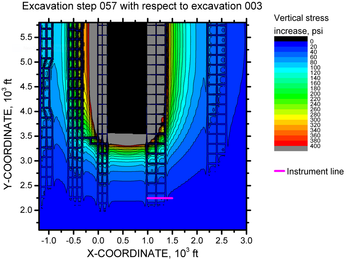
Figure 2. La MULSIM model for distribution of stress.
Figure 2 displays an Origin contour graph depicting the distribution of stress. In this example the contours show computed MULSIM model stress increase of a specific mining step with respect to pre-panel mining. This was then compared with instrument readings. The range of instrument locations is depicted by the pink line. This mining step shows the average location of the face when the instruments detected the stress increase reading of 20 psi. In the plot, the 20-psi stress increase contour line passes approximately through the location of the instruments, indicating that the rock mass stiffness for this model is calibrated to give reasonable stress profiles.

Figure 4. Comparing measured and calculated load transfer distance.
|